

Want to see how one small LED can produce different colors? 🔴🟢🔵 This Diffused RGB LED 5mm beginner project shows how the red, green, and blue pins of an RGB LED work using a simple battery circuit. Instead of using Arduino code, this test uses a 9V battery, a 220-ohm resistor, and manual wire switching to light up each color one at a time.
An RGB LED looks like a normal 5mm LED, but it has multiple color elements inside. The red, green, and blue parts are built into one LED package. By connecting power to a specific color pin, you can light up that color. This makes the RGB LED useful for indicators, decorative lights, status signals, and beginner color experiments.
This guide focuses on a simple color test. The goal is to show what happens when you connect the resistor to the red, green, or blue pin. When you move the connection, the LED changes color. This gives beginners a clear way to understand that an RGB LED is not just one LED, but three color channels inside one component.
Why Build?
This project is useful because it teaches the basic idea behind RGB lighting. Many LED strips, gaming lights, mood lamps, and electronic indicators use the same red-green-blue concept. Before using RGB LEDs with Arduino, it helps to test the colors manually first. This makes the pin behavior easier to understand.
It also teaches why a resistor is important. The resistor limits the current flowing through the LED. Without a resistor, the LED can receive too much current from the battery and get damaged. In this test, the 220-ohm resistor helps protect the LED while allowing the color to light up.
This build is also easy to demonstrate. You only need to swap the wire connection to show red, green, and blue. The result is instant, so beginners can quickly see how each pin affects the color output. It is a good starter activity before moving to PWM control or color mixing with a microcontroller.
Another reason to build it is that it introduces LED polarity. RGB LEDs have a common pin and separate color pins. If the common pin or color pin is connected incorrectly, the LED will not light. This helps beginners practice identifying LED legs and checking connections carefully.
What You’ll Learn
By building this RGB LED 5mm test, you’ll learn:
- How an RGB LED contains red, green, and blue color channels.
- How each color has its own pin.
- How the common pin works in an RGB LED.
- How a 9V battery can power a simple LED test circuit.
- Why a resistor is needed when powering an LED.
- How a 220-ohm resistor limits current in the circuit.
- How swapping the wire changes the LED color.
- How to identify if the red, green, or blue pin is connected correctly.
- How RGB LEDs can be used for indicators and decorative lighting.
- Why this manual test is helpful before using Arduino color control.
What You’ll Need
Fritzing Diagram
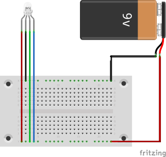
How It Works
An RGB LED works like three small LEDs inside one clear or diffused LED body. One internal LED produces red, another produces green, and another produces blue. These three color channels share one common pin. The separate color pins allow you to choose which internal LED will turn on.
The resistor protects the LED by limiting current. A 9V battery can push too much current through a small LED if there is no resistor. The 220-ohm resistor reduces that current so the LED can light without being connected directly to the battery. This is why the resistor should always stay in the circuit.
The RGB LED can also create mixed colors when more than one color channel turns on at the same time. Red and green can create yellow-like light, red and blue can create magenta-like light, and green and blue can create cyan-like light. Turning on all three can create a white or near-white color, depending on the LED brightness balance. In this beginner test, each color is shown one at a time to make the pin function clear.
Applications and Extensions
This RGB LED 5mm test is useful as a first step before building LED indicators. Once you understand the red, green, and blue pins, you can use the LED to show different status conditions. For example, red can mean error, green can mean ready, and blue can mean standby. This makes RGB LEDs useful in small electronics projects.
You can also use RGB LEDs for decorative lighting. A simple circuit can light one color at a time, while an Arduino project can fade between colors. This makes RGB LEDs useful for mood lights, small displays, mini lamps, and holiday decorations. The same concept is used in larger RGB lighting systems.
Another extension is Arduino PWM color mixing. Instead of manually moving wires, each color pin can connect to an Arduino PWM pin through a resistor. The Arduino can then control the brightness of red, green, and blue separately. By changing the brightness levels, the LED can produce many different color combinations.
You can also build a push-button color selector. One button can cycle between red, green, blue, yellow, cyan, magenta, and white. This would turn the simple battery test into a small interactive color project. It is a good next step after learning the basic RGB LED pin function.
For a cleaner final output, place the LED, resistor, and battery connector on a small perfboard or inside a simple enclosure. Label the red, green, and blue test points so users can easily switch colors. This makes the demo easier to present in a classroom, workshop, or product learning display.
Watch the Full Demo Video
Here’s the Diffused RGB LED 5mm.