
Ever tried moving several servos and the motion turns shaky or uneven? ⚙️✨ The PCA9685 16Ch Servo Driver helps by generating clean servo pulses on its own. Your Arduino only sends control commands over I2C, so the timing stays steady. This makes multi-servo tests feel much more stable. It also keeps your wiring cleaner than using many Arduino pins.
For this tutorial, you will use an Arduino, one PCA9685 board, and four servos. You will plug the servos into channels 4, 5, 6, and 7 on the driver. You will power the servos from a solid 5V source instead of the Arduino’s 5V pin. You will also connect a shared ground so the signals have a clear reference. This setup matches the code exactly and keeps the test simple.
The goal is a clear “pass or fail” motion test you can see right away. The sketch moves the servos to 0°, then 90°, then 180°, with pauses between each step. That pattern makes it easy to spot a loose plug, a wrong channel, or a weak power rail. Serial messages print the target angle so you can confirm the loop is running. Once this works, you can expand to more channels with the same method.
Why Build?
The biggest reason is pin and wiring simplicity. With the driver, you do not burn many Arduino pins just to run servos. You can keep your Arduino pins free for sensors, buttons, and screens. That matters when your project grows beyond a small demo. It also makes your wiring layout easier to track during setup.
The second reason is more stable motion when your sketch gets busy. Servo control needs precise pulse timing, and heavy code can cause jitter on some setups. The driver keeps output timing steady because it handles the pulses on its own. Your Arduino can handle logic without “stealing time” from servo signals. This helps a lot once you add sensors, menus, or wireless code.
The third reason is easier troubleshooting with a clean baseline. A repeatable sweep test tells you if channels, plugs, and power are healthy. If all four servos move the same way, the core system is likely good. If one servo fails, you can swap it to another channel and learn more fast. This saves time before you mount horns, linkages, or heavy loads.
What You’ll Learn
- I2C basics – SDA/SCL wiring and why one bus can control many channels.
- Driver address – why 0x40 is common and when it changes.
- Channel control – using channel numbers instead of Arduino signal pins.
- Servo rate – why 50 Hz is the normal servo update frequency.
- Pulse limits – what SERVOMIN and SERVOMAX represent in real motion. Angle mapping – converting 0 – 180° into a pulse value the driver can output.
- Group motion pattern – moving channels 4 – 7 together for a fast health check. Power rules – why servos need a solid 5V rail and shared ground.
- Quick fault checks – how to spot weak power, a bad plug, or a bad servo fast.
Parts in this build
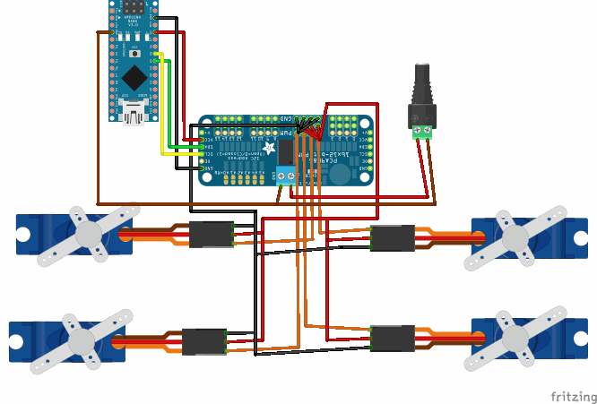
Fritzing Diagram

Wiring Connection
Arduino Nano to PCA9685
Nano 5V → PCA9685 VCC
Nano GND → PCA9685 GND
Nano A4 → PCA9685 SDA
Nano A5 → PCA9685 SCL
External 5V power for servos
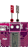
External 5V positive (+) → PCA9685 V+
External 5V negative (-) → PCA9685 GND
Important:
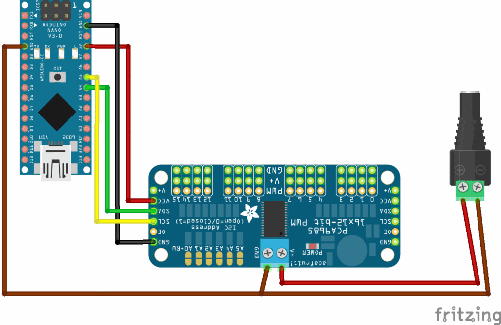
Nano GND + PCA9685 GND + External power GND
Sample Code
This sketch needs Wire (built-in with Arduino IDE) for I2C communication, and Adafruit PWM Servo Driver Library for the PCA9685 control. In the Arduino IDE,
- go to Sketch → Include Library → Manage Libraries, then search and install “Adafruit PWM Servo Driver” (it will also pull Adafruit BusIO if needed). After installing, select the correct board and port, then paste the code and upload.
#include <Wire.h>
#include <Adafruit_PWMServoDriver.h>

Adafruit_PWMServoDriver pwm = Adafruit_PWMServoDriver(0x40);

// Good starting values for SG90
#define SERVOMIN 110
#define SERVOMAX 500

void setup() {
  Serial.begin(9600);

  pwm.begin();
  pwm.setPWMFreq(50); // Servo frequency

  delay(500);
  Serial.println("PCA9685 Servo Test");
}

void loop() {
  moveAllServos(0);
  delay(1000);

  moveAllServos(90);
  delay(1000);

  moveAllServos(180);
  delay(1000);
}

void moveAllServos(int angle) {
  setServoAngle(4, angle);
  setServoAngle(5, angle);
  setServoAngle(6, angle);
  setServoAngle(7, angle);

  Serial.print("Angle: ");
  Serial.println(angle);
}

void setServoAngle(int channel, int angle) {
  int pulse = map(angle, 0, 180, SERVOMIN, SERVOMAX);
  pwm.setPWM(channel, 0, pulse);
}
How It Works
The sketch starts by setting up the driver on I2C. It calls pwm.begin() to start the PCA96685 and then sets pwm.setPWMFreq(50) for servo use. That 50 Hz setting matches what most hobby servos expect. After a short delay, the sketch prints a message so you know setup finished. If setup fails, servos usually do nothing, which makes the issue easy to notice.
Servos do not “understand degrees” directly, so the code converts angles into pulse lengths. The driver outputs pulses using a tick range, and your code picks a safe range with SERVOMIN and SERVOMAX. The map() call turns an angle like 90° into a pulse value inside that range. Then pwm.setPWM(channel, 0, pulse) sends that pulse to one channel. This keeps control consistent across channels without manual math each time.
The loop creates a simple motion routine that is easy to watch. It calls moveAllServos(0), waits, then moveAllServos(90), waits, then moveAllServos(180), and waits again. Inside moveAllServos(), only channels 4, 5, 6, and 7 are updated, so the test stays focused. Serial prints the target angle each step so you can confirm the pattern. If one servo moves late or not at all, you can inspect that channel first.
Applications & Extensions
After this test, you can build multi-servo rigs with much less wiring stress. The PCA9685 16Ch Servo Driver fits robot arms, pan-tilt heads, walking bots, and animatronic props. You can add more servos by plugging them into new channels and calling the same helper function. Your code stays tidy because channel numbers are easy to manage. This also makes it good for quick servo batch testing.
Next, improve motion quality so it looks smooth and safe. Instead of jumping from 0° to 180°, you can move in small steps with short delays. You can also add per-servo offsets so each servo’s “center” matches your real mount position. This helps when horns are not installed perfectly straight. You can also stagger motion across channels to reduce current spikes. These changes make your build feel more “real” and less abrupt.
When you need more scale, you can run more than one PCA96685 board. Many boards support different I2C addresses using solder jumpers. That lets you add more channels on the same SDA/SCL lines. You still must keep servo power strong and grounds shared across the whole system. With good power and clean wiring, scaling up becomes a simple, repeatable process.
Watch the Full Demo Video
Here’s the PCA9685 16Ch Servo Driver