
Ever wished your Arduino could “talk back” when you move a joystick? In this tutorial, you will build a clean direction viewer that prints UP, DOWN, LEFT, RIGHT, or CENTER on a 16×2 I2C LCD as you move the stick. This makes joystick behavior easy to confirm without guessing or staring at the Serial Monitor. By the end, you will have a working setup you can reuse as an input module for bigger builds like robots and menus.
A thumb joystick outputs two analog signals, one for the X axis and one for the Y axis. Your Arduino reads those signals on A0 and A1 as values from 0 to 1023. The sketch compares each value against threshold limits to decide which direction is active. The LCD then shows the result in a simple, readable way that anyone can test in seconds.
This guide focuses on wiring basics, stable readings, and clean LCD updates. It uses the LiquidCrystal_I2C library and a common LCD address like 0x27. It also avoids flicker by updating the display only when the direction changes. That small detail makes the output look smooth and professional during demos.
Once you can read joystick directions on the LCD, you can use the same input logic to control real motion. A great next step is moving a servo using the joystick, where LEFT/RIGHT or UP/DOWN maps to angle changes. Check this related tutorial here: Controlling Servo Movement with a Joystick Using Arduino Uno. It’s a natural upgrade because you already understand the joystick range and direction rules.
Why Build?
This tutorial is a fast way to verify that your joystick and I2C LCD are wired correctly. Many beginner problems come from the wrong LCD address, swapped SDA/SCL pins, or connecting the joystick to the wrong analog inputs. With this setup, you will immediately see whether movement matches the printed direction on the screen. That saves time before you move on to motors, robotics, or wireless control.
It also teaches how analog inputs behave in the real world. A joystick rarely sits at one exact center value, and readings can drift because of noise, wiring, or power changes. Because of that, this tutorial uses threshold ranges instead of expecting one perfect number. You learn how a center deadzone keeps controls stable and prevents random direction flicker.
Finally, it gives you a strong base for many beginner control systems. Direction outputs map cleanly to actions like “turn left,” “move up,” or “scroll down.” The LCD feedback makes testing simple because you can see results without a laptop connected. Once you trust your input, the rest of your project becomes much easier to debug and improve.
What You’ll Learn
- Thumb joystick basics – How VRx (X) and VRy (Y) change as analog values from 0 – 1023.
- Reading two axes – Why A0 reads X and A1 reads Y, and what “center” usually looks like.
- Direction thresholds – How the 300/700 limits turn raw values into LEFT/RIGHT/UP/DOWN decisions.
- Priority logic – Why the code checks X first, then Y, and how that affects diagonal pushes.
- Flicker-free LCD updates – How
lastDirectionprevents constant clearing and keeps the screen stable. - I2C LCD essentials – What SDA/SCL do, and why changing 0x27 to 0x3F can fix a blank display.
- Simple tuning – How to adjust thresholds if your joystick center drifts or your range is different.
- Next-step control – How the same direction output can drive menus, servos, or robot movement.
What You'll Need
Fritzing Diagram
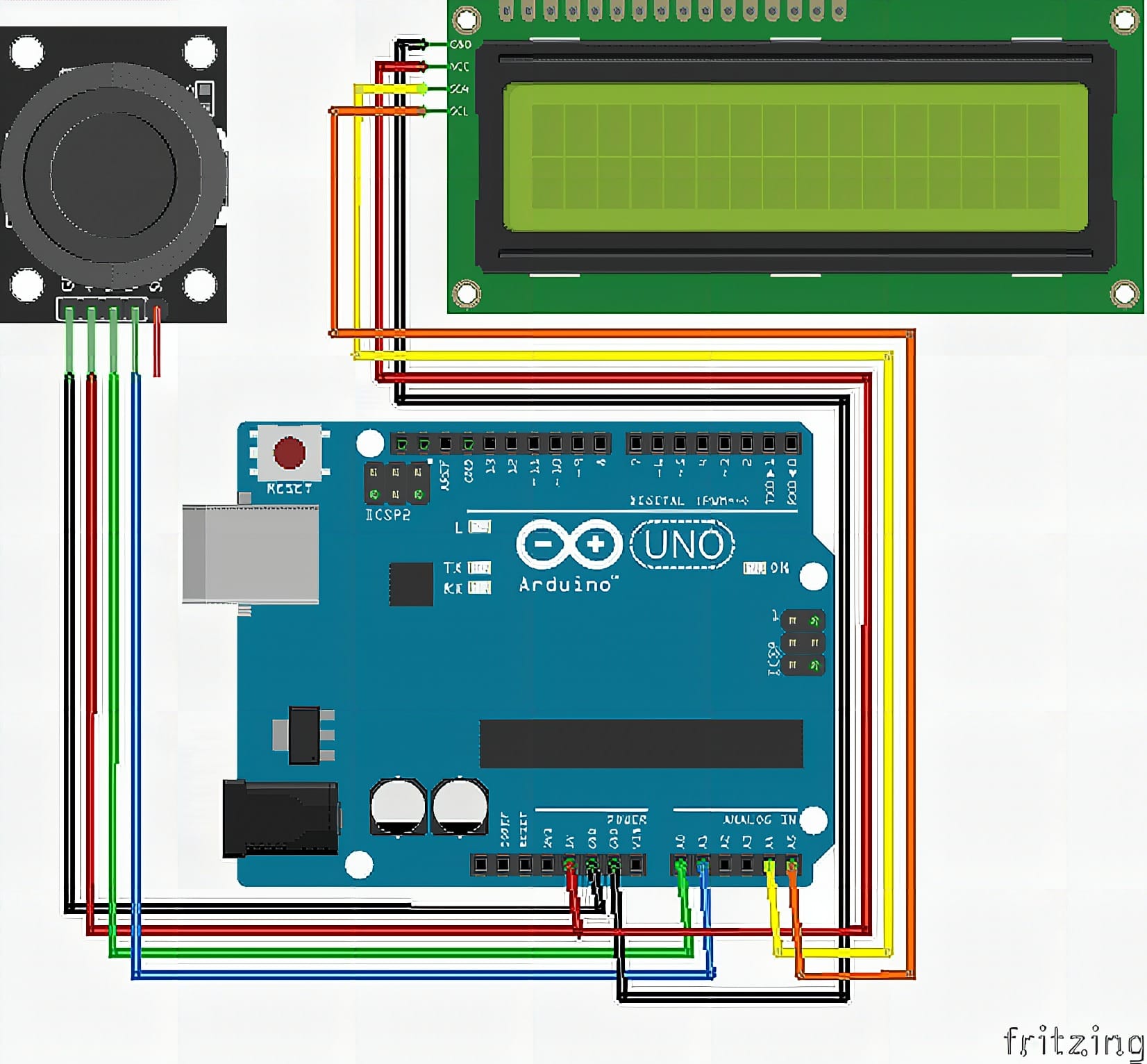
Wiring Connections
Joystick Module to Arduino
- VRx / X OUT → A0
- VRy / Y OUT → A1
- VCC → 5V
- GND → GND
16×2 I2C LCD to Arduino
- VCC → 5V
- GND → GND
- SDA → A4
- SCL → A5
Sample Code
#include <Wire.h>
#include <LiquidCrystal_I2C.h>

// Change 0x27 to 0x3F if your LCD does not display anything
LiquidCrystal_I2C lcd(0x27, 16, 2);

// Joystick pins
const int xPin = A0;
const int yPin = A1;

// Joystick readings
int xValue = 0;
int yValue = 0;

// Last displayed direction
String lastDirection = "";

void setup() {
  lcd.init();
  lcd.backlight();

  lcd.setCursor(0, 0);
  lcd.print("Joystick Ready");

  delay(1000);
  lcd.clear();
}

void loop() {
  xValue = analogRead(xPin);
  yValue = analogRead(yPin);

  String direction = "CENTER";

  if (xValue < 300) {
    direction = "LEFT";
  }
  else if (xValue > 700) {
    direction = "RIGHT";
  }
  else if (yValue < 300) {
    direction = "DOWN";
  }
  else if (yValue > 700) {
    direction = "UP";
  }

  if (direction != lastDirection) {
    lcd.clear();

    lcd.setCursor(0, 0);
    lcd.print("Direction:");

    lcd.setCursor(0, 1);
    lcd.print(direction);

    lastDirection = direction;
  }

  delay(100);
}
How It Works
When the Arduino powers up, the sketch initializes the LCD, turns on the backlight, and prints a short “Joystick Ready” message. This confirms the LCD is responding over I2C and that the address in your code matches your module. After a short delay, the LCD clears so the main direction screen starts clean. If you see nothing at this stage, you can focus your troubleshooting on I2C wiring and address first.
In the main loop, the Arduino reads xValue from A0 and yValue from A1. The code starts with “CENTER” by default, then checks the values against threshold limits. If X is far enough left or right, it prints LEFT or RIGHT; if X is centered, it uses Y to decide UP or DOWN. This order makes sideways movement take priority during diagonal pushes, which is a simple and predictable rule for beginners.
The LCD only updates when the direction changes, which keeps the screen steady. The sketch compares the new direction to lastDirection before clearing and rewriting the display. This reduces flicker and prevents the LCD from being spammed every cycle. A short delay slows updates so the text stays readable and the readings have time to settle. If your joystick behaves differently, you can tune the 300 and 700 threshold values to fit your real range.
Applications & Extensions
After you complete this tutorial, you can use the setup as a quick joystick tester for future builds. It helps you confirm the joystick returns to center and does not drift into a false direction when released. It also makes threshold tuning easier because you see direction changes instantly as you move the stick. This is especially useful before you connect motors where wrong input can cause sudden movement.
You can extend this into a simple menu controller on the same LCD. Map UP/DOWN to move through menu items, and map LEFT/RIGHT to change values like speed, brightness, or mode. If your joystick module includes a push switch, you can add it as a “select” button for confirming choices. With that, you gain a complete input-and-display UI without adding extra sensors.
For more advanced control, add richer feedback and smoother logic. Display raw X and Y values for a calibration mode, then switch back to direction mode for normal use. Detect diagonals by checking X and Y together and printing combined directions like “UP-LEFT.” You can also send direction over Bluetooth, RF, or Serial to control another board remotely. These upgrades keep the same core reading pattern, so you build directly on what you already verified.
Watch the Full Demo Video
Here’s the Thumb Joystick.
Frequently Asked Questions
What does this Thumb Joystick tutorial cover?
Ever wished your Arduino could “talk back” when you move a joystick? In this tutorial, you will build a clean direction viewer that prints UP, DOWN, LEFT, RIGHT, or CENTER on a 16×2 I2C LCD as you move the stick.
What Arduino library does the Thumb Joystick tutorial use?
The sketch uses standard Wire.h (I2C) or SPI.h plus a part-specific library installable via Arduino IDE → Sketch → Include Library → Manage Libraries. See the Sample Code section.
Why does the Thumb Joystick act differently on USB power vs battery?
Battery voltage sags under load. Add a 100uF cap across the rails, use a 5V/2A regulator-backed pack, and never power motors from the Arduino's onboard regulator.