

Running out of pins? Imagine reading 16 sensors with only one Arduino input. That’s what the HP4067 does:. ⚙️⚡ It selects one channel (C0–C15) and routes it to SIG. Your Arduino then reads SIG as if the sensor were wired directly, which keeps wiring simple.
Although the chip says “analog,” it also carries digital 0–VCC signals. You can connect SIG to A0 and use analogRead() for variable voltages. Or you can connect SIG to a digital pin and use digitalRead() for HIGH / LOW modules such as IR obstacle sensors. Either way, you read one channel at a time.
In this tutorial, you will wire a few channels and drive S0–S3 to pick inputs. Then you will add a short settle delay and read values in a loop. Finally, you will see how to scale from two inputs to all 16 without changing the core pattern.
Why Build Arduino Analog Multiplexer?
You gain more inputs with fewer pins, so you can stay on an Uno or Nano. One SIG line plus four select pins unlocks 16 sources. As a result, dashboards with knobs, LDRs, and IR sensors become practical.
Your wiring gets cleaner and shorter, which boosts reliability. All sensor leads meet at the MUX, and only one signal runs back to the Arduino. Therefore, enclosures close easier and breadboards look organized.
The design grows with your project. Start small and expand later. Because the pattern stays the same—select, settle, read—you can mix analog and digital sensors and still keep the code tidy.
What You’ll Learn
By building this Arduino Analog Multiplexer, you’ll:
Concept: The HP4067 routes one C0–C15 input to SIG so the Arduino can read it.
Addressing: Drive S0–S3 like a 4-bit number (0–15). Keep EN/¯E LOW to enable the chip.
Two read styles:
- Analog: SIG→A0, then
analogRead()for pots, LDR dividers, and voltage-output sensors. - Digital: SIG→Dx, then
digitalRead()for HIGH/LOW modules like IR obstacle sensors.
Stable reads: Insert a short settle delay after switching and use averaging or thresholds when values jitter.
Limits & safety: Read one channel at a time, share ground, keep signals within 0–VCC, and avoid fast buses such as I²C/SPI.
Scaling: Loop through channels 0–15, add per-channel calibration, or combine multiple MUX chips.
What You’ll Need:
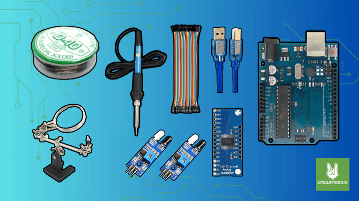
- Analog Multiplexer HP4067
- IR Proximity Obstacle
- Arduino Uno
- Type B Cable
- Jumper Wires
- Solder Iron
- Third Hand
- Solder Lead
Arduino Analog Multiplexer Circuit Diagram
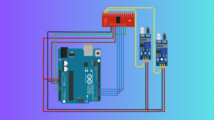
MUX:
- VCC → 5V
- GND → GND
- SIG → A0
- EN → GND
- S0 → D2
- S1 → D3
- S2 → D4
- S3 → D5
IR Proximity Obstacle:
- VCC → 5V
- GND → GND
- OUT → C1 and C2
Sample Code
// ------------------------------
// CD74HC4067 MUX CONTROL PINS
// These 4 pins select which channel (C0–C15) will be read.
// ------------------------------
const int S0 = 2;
const int S1 = 3;
const int S2 = 4;
const int S3 = 5;

// The SIG pin of the MUX is connected to Arduino A0.
// This is where the selected channel’s signal is routed.
const int SIG_PIN = A0;


// ----------------------------------------------------------
// Function: selectChannel(ch)
// Selects which MUX channel (0–15) to read.
// The channel number is decoded into 4 bits for S0–S3.
// ----------------------------------------------------------
void selectChannel(byte ch) {
  digitalWrite(S0, ch & 0x01);            // Bit 0 → S0
  digitalWrite(S1, (ch >> 1) & 0x01);     // Bit 1 → S1
  digitalWrite(S2, (ch >> 2) & 0x01);     // Bit 2 → S2
  digitalWrite(S3, (ch >> 3) & 0x01);     // Bit 3 → S3
}


// ----------------------------------------------------------
// Function: readMuxChannel(ch)
// Switches to the selected channel, waits briefly,
// then reads the analog value from that channel.
// ----------------------------------------------------------
int readMuxChannel(byte ch) {
  selectChannel(ch);          // Choose which MUX channel to read
  delay(5);                   // Allow signal to stabilize
  return analogRead(SIG_PIN); // Read the value on SIG
}


void setup() {
  Serial.begin(9600);

  // Set MUX control pins as outputs
  pinMode(S0, OUTPUT);
  pinMode(S1, OUTPUT);
  pinMode(S2, OUTPUT);
  pinMode(S3, OUTPUT);

  Serial.println("CD74HC4067 Testing: Reading C1 and C2 from one proximity sensor");
}


void loop() {
  // Read the sensor value from channel C1
  int valC1 = readMuxChannel(1);

  // Read the sensor value from channel C2
  int valC2 = readMuxChannel(2);

  // Print both results side-by-side
How It Works?
Inside the HP4067 sit tiny electronic switches. When you set a number on S0–S3, the chip connects that C pin to SIG. The Arduino reads SIG, so it receives the value from that one selected sensor. Because only one path is active, the signal stays clear.
For analog reading, wire SIG → A0 and choose a channel in code. Next, wait a few milliseconds so the node can settle. Then call analogRead(A0) and store or print the result. This approach fits sliders, light sensors, and other voltage sources.
For digital reading, wire SIG → a digital pin such as D8. After selecting a channel and a brief settle, call digitalRead(D8) and check for HIGH or LOW. Many IR obstacle boards read LOW when an object is present, so invert the logic if needed. With that, you can scan several digital modules through a single pin
Applications & Extensions
Create a sensor panel for music, art, or classrooms. For example, map 12 knobs to MIDI, or read a grid of LDRs for a light wall. Because the wiring is compact, setup stays approachable.
Test robot sensors without using many pins. You can route several IR modules through the MUX and save the remaining pins for motors and servos. Then, log detections to Serial and tune thresholds with confidence.
Add upgrades as you grow. Show live bars on an OLED, trigger alarms at set levels, or stream scans to the Serial Plotter. If you need simultaneous sampling or higher precision later, add another MUX on a second pin or step up to a multi-channel ADC.


