
Don’t wait until your full project is done to find out your BTS7960 43A motor driver has a problem. A fast bench test can catch wiring mistakes, weak power, or bad behavior before they cost you time and parts. This guide uses a short Arduino sketch that makes the motor run forward, stop, reverse, and stop again in a loop. With that simple pattern, you can quickly see if the driver responds well, the motor switches direction correctly, and the setup is ready for a bigger build.
This kind of first test is useful because many motor issues do not come from the code alone. In many cases, the real problem is loose wiring, missing shared ground, mixed-up pins, or a power source that cannot support the motor well. By starting with a short and focused test, you remove extra guesswork and make the results easier to understand. If the motor behaves as expected here, you can move to a larger build with more confidence.
In this tutorial, the goal is not to build a full motor control system right away. The goal is to prove that the driver, motor, and wiring all work together in a clean and simple way. The sketch uses two PWM pins, RPWM and LPWM, to drive one direction at a time, with short stops in between. That makes the movement easy to observe and helps reduce stress on the motor and driver during direction changes. If you want to explore more beginner-friendly microcontroller guides, you can also read Raspberry Pi Pico (RP2040) | A Beginner’s Guide
Why Build?
This quick test helps you confirm your BTS7960 43A works before you commit it to a bigger build. It runs a simple forward and reverse cycle, so you can see direction switching and basic speed response right away. That saves you time because you don’t have to debug motors, wiring, and project logic all at once. It also helps you catch loose connections early, before they heat up or fail under load.
It also protects your parts and your budget. A faulty driver, weak power supply, or wrong pin mapping can waste hours and sometimes damage a motor. With a short, repeatable test loop, you can isolate problems faster and avoid guessing. You’ll also learn what “normal” behavior looks like, so later issues stand out immediately.
Finally, it gives you a clean baseline for troubleshooting. If the driver passes this test, you can move on to buttons, joystick control, or PID speed control with more confidence. If it fails, you know the problem is likely power, wiring, or the module itself – not your future project code. That makes your next steps clearer and keeps the whole article easy to follow.
What You’ll Learn
- Basic BTS7960 test flow – Run a simple forward → stop → reverse → stop loop to validate behavior fast.
- RPWM vs LPWM control – Drive only one PWM input at a time to set direction safely and clearly.
- PWM speed control – Use
analogWrite()values (0 – 255) to change motor speed during testing. - Clean direction switching – Add a stop delay between direction changes to reduce stress and spikes.
- Wiring checks that matter – Confirm shared ground, correct RPWM/LPWM pins, and solid motor terminals.
- Power source reality – Learn why weak supplies cause stutter, resets, or a motor that won’t start.
- Defect signs vs setup issues – Spot “one direction only,” overheating, or no response and know what to check next.
What You'll Need
Fritzing Diagram
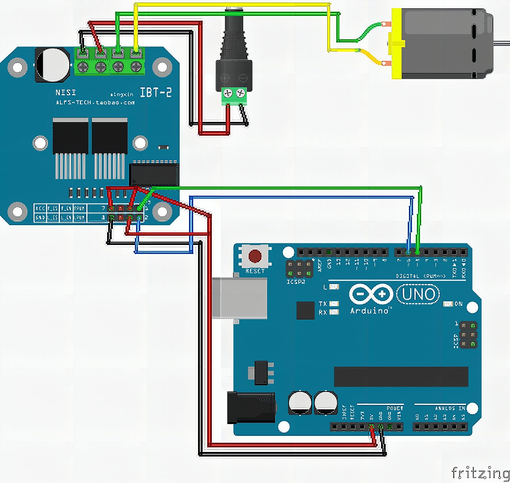
Wiring Connections
Arduino to BTS7960
D5→RPWMD6→LPWM5V→VCCGND→GND5V→R_EN5V→R_EN
Motor Power and Motor Wiring
- Power supply 12v+ → BTS7960 B+
- Power supply 12v- → BTS7960 B-
- Motor wire 1 → BTS7960 M+
- Motor wire 2 → BTS7960 M-
Do not power the motor driver from the Arduino 5V pin. Use External powersuply 12v
Sample Code
// BTS7960 Basic Forward/Reverse Test (RPWM/LPWM)

const int RPWM = 5;
const int LPWM = 6;

void setup() {
  pinMode(RPWM, OUTPUT);
  pinMode(LPWM, OUTPUT);

  // Start stopped
  analogWrite(RPWM, 0);
  analogWrite(LPWM, 0);
  delay(500);
}

void loop() {
  // Forward (about 70% speed)
  analogWrite(RPWM, 180);
  analogWrite(LPWM, 0);
  delay(2000);

  // Stop
  analogWrite(RPWM, 0);
  analogWrite(LPWM, 0);
  delay(1000);

  // Reverse (about 70% speed)
  analogWrite(RPWM, 0);
  analogWrite(LPWM, 180);
  delay(2000);

  // Stop
  analogWrite(RPWM, 0);
  analogWrite(LPWM, 0);
  delay(1000);
}
How It Works
The sketch sets RPWM (pin 5) and LPWM (pin 6) as outputs and starts with both at zero. That ensures the driver is in a neutral state before the motor moves. A short delay after initialization helps the system settle before the first command.
In the main loop, the code drives forward by sending a PWM value (180 ≈ 70%) to RPWM while keeping LPWM at 0. After two seconds, it stops by setting both outputs to zero. Then it reverses by switching: LPWM gets the same PWM value while RPWM stays at 0, followed by another stop.
This pattern creates a simple, repeatable test cycle. If the wiring is correct and the module is healthy, the motor will spin one direction, stop cleanly, then spin the other direction. If the motor only spins one way, stutters, or the driver overheats quickly, you can narrow the issue to wiring, power, PWM pins, or a faulty board.
Applications & Extensions
Use this as your incoming inspection test for every BTS7960 module. You can confirm it works before installing it into robots, scooters, linear actuators, or heavy-load gear motors. It’s also a great “known-good” test when a motor system suddenly stops working.
Next, extend it to real controls. Add R_EN/L_EN pins if your board exposes them, and implement braking, coast, and smooth ramp-up/ramp-down. You can also read current/temperature externally to validate safe operation under load.
Finally, build full projects on top of it. Control speed with a potentiometer, add direction buttons, or integrate RC/joystick input. Once you trust the driver, you can safely scale into higher voltage motors and heavier loads – while keeping the same forward/stop/reverse logic as your debugging tool.
Watch the Full Demo Video
Here’s the Motor Drive (BTS7960 43A).
Frequently Asked Questions
What does this Motor Drive (BTS7960 43A) tutorial cover?
Don’t wait until your full project is done to find out your BTS7960 43A motor driver has a problem.
What Arduino library does the Motor Drive (BTS7960 43A) tutorial use?
The sketch uses standard Wire.h (I2C) or SPI.h plus a part-specific library installable via Arduino IDE → Sketch → Include Library → Manage Libraries. See the Sample Code section.
Why does the Motor Drive (BTS7960 43A) act differently on USB power vs battery?
Battery voltage sags under load. Add a 100uF cap across the rails, use a 5V/2A regulator-backed pack, and never power motors from the Arduino's onboard regulator.