

Press power, watch color happen. This beginner-friendly Arduino LED Matrix project drives a 64-pixel (8×8) NeoPixel matrix from an Arduino and paints it with a smooth, rotating rainbow. All pixels sweep through the hue together, creating a clean, screen-wide wash that feels alive. It’s the perfect “first light” for anyone new to addressable LEDs.
You’ll use the Adafruit NeoPixel library with a tiny loop that picks a color, fills the whole matrix, and advances the hue every few milliseconds. The sketch exposes two knobs – BRIGHTNESS and SPEED – so you can balance look, motion, and power draw. With just one data wire on D6 and a few lines of code, you can push a surprisingly rich, polished effect.
Because the build is simple, you can focus on fundamentals rather than complexity. You’ll see how a single microcontroller pin can coordinate many RGB LED with precise timing. Once the basic rainbow is running, you’ll be ready to branch into patterns, sensors, and interactive ideas without rebuilding everything from scratch.
The same 8×8 NeoPixel matrix is also used in the Touch-o-Lantern, where it creates a dramatic red-light glow effect instead of a rainbow. In that build, the matrix enhances the Halloween mood by reacting to touch input and lighting up the lantern with an eerie red illumination.
Why Build?
This LED matrix build gives you a fast, satisfying first win with addressable LEDs. You get smooth color motion with only one data pin and a few lines of code. It’s also a great “hardware check” because you’ll see right away if power, ground, and DIN are correct. Once it runs, you know your matrix and wiring are ready for bigger effects.
It also teaches the core ideas behind most NeoPixel projects. You learn how brightness limits affect power draw and stability. You learn how timing (delay speed) changes the feel of an animation. Those two knobs let you tune the look without rewriting the logic.
Finally, it’s an easy base for upgrades. You can go from “whole panel same color” to per-pixel patterns without changing your wiring. You can also reuse the same matrix for themed builds like Touch o Lantern by changing only the effect. That makes this tutorial useful beyond a single rainbow demo.
What You’ll Learn
- NeoPixel basics – how one data pin controls many RGB LEDs.
- Library setup – using
Adafruit_NeoPixelwith the correct pixel count and pin. - Hue cycling – converting a 0 – 255 value into RGB colors using a color wheel.
- Full-panel fill – using
strip.fill()to paint all 64 pixels at once. - Animation timing – using a counter +
delay(SPEED_MS)for steady motion. - Brightness control – using
setBrightness()to limit output and power draw. - Directional wiring idea – why you must feed data into DIN, not DOUT.
- Next-step patterns – how this becomes the base for waves, gradients, and interactive effects.
Parts in this build
Fritzing Diagram
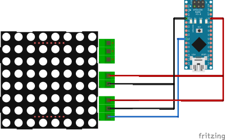
For a single 8×8 at modest BRIGHTNESS, you can power the matrix from the Nano’s 5 V pin and split that 5 V and GND to the two power pads on the panel. Splitting the wires does not increase total current; it simply feeds both sides so voltage is distributed more evenly across the board. With short leads and sensible brightness, this is a practical way to keep parts to a minimum for quick builds and classroom demos.
Keep expectations realistic as you test scenes. Full-white frames draw far more current than rainbow washes, so treat flicker or resets as a sign to lower BRIGHTNESS or upgrade the power source. If you later want brighter scenes or chained panels, move the LEDs to a dedicated 5 V supply sized for the load and keep Arduino GND tied to LED GND so the data signal has a solid reference.
The circuit diagram should show three essentials: a single data line from D6 to the matrix’s data input, a common ground between the Arduino and the matrix, and the split 5 V/GND feeding both power pads on the panel. Keep the data run short and the power leads appropriately thick for the current you expect. This small attention to layout pays off with stable colors and smooth motion.
Sample Code
#include <Adafruit_NeoPixel.h>

#define LED_PIN     6
#define NUMPIXELS   64
#define BRIGHTNESS  40   // 0..255
#define SPEED_MS    15   // smaller = faster

Adafruit_NeoPixel strip(NUMPIXELS, LED_PIN, NEO_GRB + NEO_KHZ800);

uint32_t wheel(byte pos) {
  pos = 255 - pos;

  if (pos < 85) {
    return strip.Color(255 - pos * 3, 0, pos * 3);
  }

  if (pos < 170) {
    pos -= 85;
    return strip.Color(0, pos * 3, 255 - pos * 3);
  }

  pos -= 170;
  return strip.Color(pos * 3, 255 - pos * 3, 0);
}

void setup() {
  strip.begin();
  strip.setBrightness(BRIGHTNESS);
  strip.show();  // clear on start
}

void loop() {
  static uint16_t j = 0;

  // All pixels share the same color; hue rotates over time
  uint32_t c = wheel(j & 255);
  strip.fill(c);
  strip.show();

  j++;
  delay(SPEED_MS);
}
How It Works
The matrix is an array of individually addressable RGB LEDs that share power and a single data line. The Arduino sends a carefully timed waveform; each LED takes its own 24-bit color, then passes the rest downstream. Because LEDs latch their colors, you only transmit again when you want the image to change.
In the provided sketch, a small wheel() helper converts a byte (0 – 255) into an RGB value that walks around the hue circle. The loop increments a counter j, computes a color with wheel(j & 255), fills all 64 pixels, and shows the result. A brief delay (for example, SPEED_MS = 15) controls how quickly the hue advances, so lowering the number speeds up the animation.
Two constants tame behavior without touching the effect math. BRIGHTNESS (0 – 255) limits LED output so panels stay cool and supplies stay happy, while SPEED shapes the feel of the motion. The end result is a global hue wash – every pixel matches while the color morphs – perfect for learning before you step into per-pixel maps and sprites.
Matrix Connector Map:
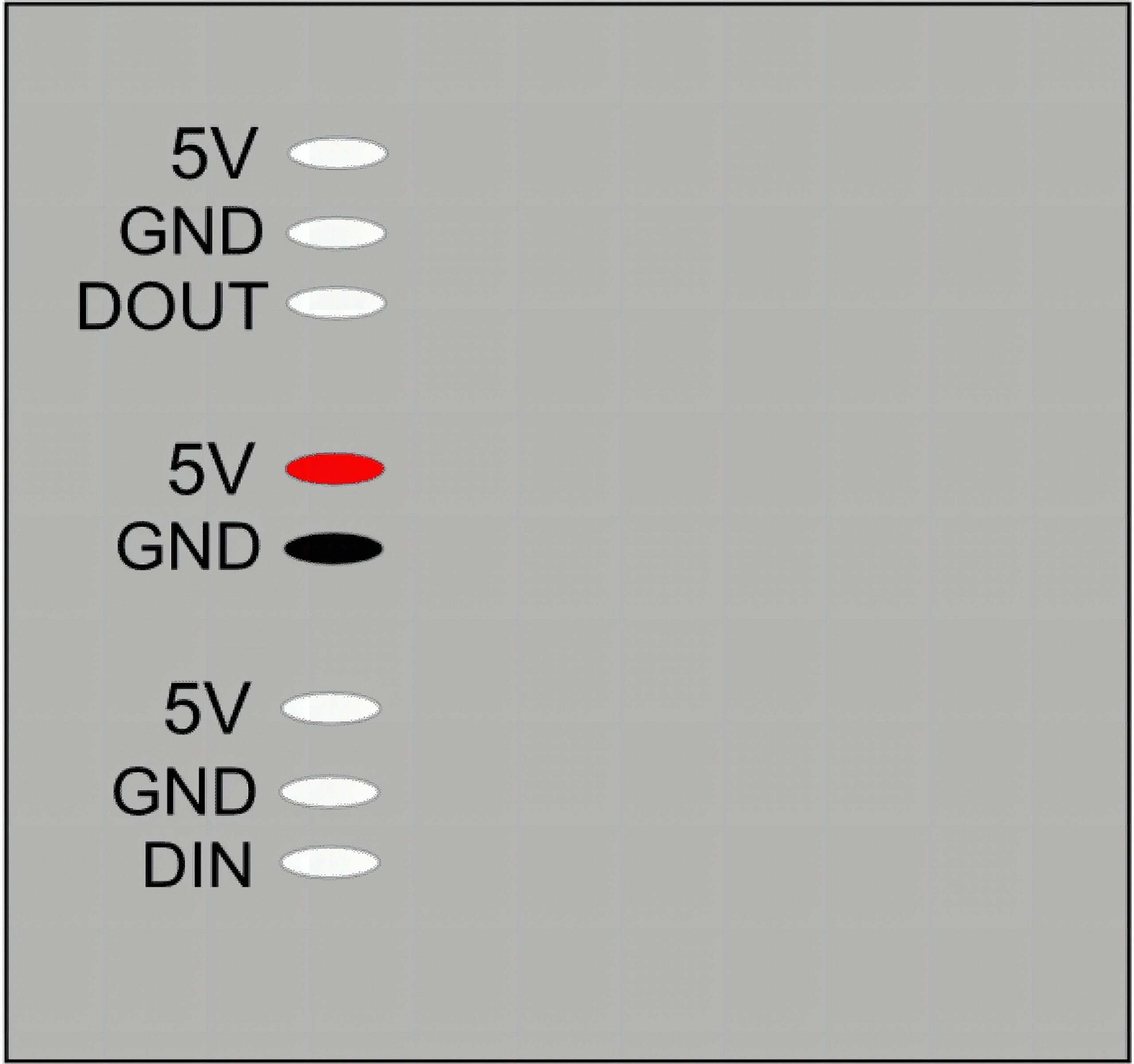
Addressable matrices are directional pipelines. Data must enter at DIN, flow through each LED, and exit at DOUT for optional chaining. That’s why the panel exposes DIN on one side (start of the pipeline) and DOUT on the other (end of the pipeline). Following the arrows prevents scrambled patterns or a display that never starts.
You’ll also see power pads on both ends – that’s for power injection. As current travels along thin copper traces, voltage drops and far pixels can dim, especially during bright or white scenes. Feeding 5 V/GND from both sides shortens the path resistance and keeps brightness uniform; a single 8×8 at modest brightness is fine from one end, while full-white tests or chained tiles benefit from dual-end power.
When chaining panels, route DOUT → DIN between tiles for data, and consider injecting power near the far end to avoid drop across the run. Always keep microcontroller and LED grounds common so the data signal has a stable reference. Keeping wiring short and secure dramatically improves reliability without complicating the build.
Applications & Extensions
Turn the matrix into an ambient status tile: green when a task is OK, blue while waiting, red on error, and rainbow while busy. A quick glance across the room tells you what’s happening, and the subtle wash plays nicely on a desk or shelf. As you iterate, you can tune speed and brightness for the environment.
Evolve the animation into pixel-level patterns. Replace fill() with a double loop and offset each pixel’s hue by its x/y position for flowing rainbows, diagonal wipes, or plasma-style maps. Add a potentiometer to adjust speed live, or a button to flip between modes, so the matrix becomes interactive.
Bridge to interactive builds. Drive brightness from a microphone level, map a temperature sensor to color, or render tiny game sprites and text. The same wiring and library calls scale to clocks, word displays, Tetris, or scrolling marquees – this starter gives you a solid, safe foundation.
Watch Related Project
Frequently Asked Questions
What does this Arduino LED Matrix tutorial cover?
Press power, watch color happen.
What Arduino library does the Arduino LED Matrix tutorial use?
The sketch uses standard Wire.h (I2C) or SPI.h plus a part-specific library installable via Arduino IDE → Sketch → Include Library → Manage Libraries. See the Sample Code section.
Why does the Arduino LED Matrix act differently on USB power vs battery?
Battery voltage sags under load. Add a 100uF cap across the rails, use a 5V/2A regulator-backed pack, and never power motors from the Arduino's onboard regulator.