

In this tutorial, you’ll be building an Arduino GPS Location Tracker using the NEO-6M GPS module. The GPS Flight Control Module serves as a key component in navigation and tracking applications. This type of project is great for learning how GPS works. You can integrate the GPS NEO6MV2 module into various applications like tracking devices, navigation systems, or logging outdoor activities
The purpose of this project is to create a simple and reliable GPS tracker that can provide live location data. You will connect the NEO-6M to your Arduino, which will read and process the GPS signals. It displays the data on the serial monitor. The NEO-6M receives signals from satellites to determine your exact position. People often use this module in projects like car tracking systems, drones, and portable GPS devices. With this project, you’ll explore how GPS data can be captured and displayed in real-time using the Arduino platform.
This project teaches you several important concepts. First, you’ll understand how GPS technology works, including how devices communicate with satellites to determine location. You will gain practical experience in connecting and programming hardware components with Arduino. You will learn how to handle real-time data and display it in a readable format. This project will teach you how to track location data and give you a deeper understanding of integrating similar modules into larger, more complex systems.
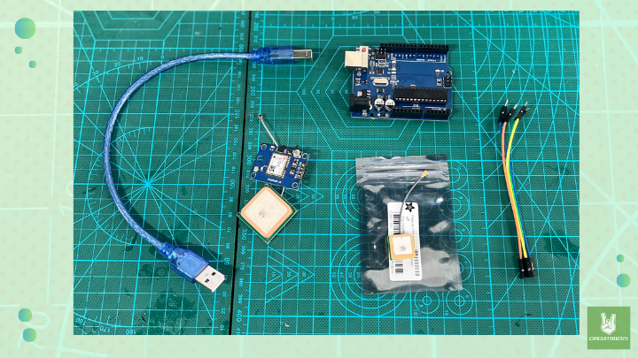
Components:
If you’re working on a GPS location tracker project using the NEO6MV2 module, the Antenna Passive GPS uFL – 15mm x 15mm is an excellent alternative for enhancing your build. This compact antenna is ideal for anyone looking to maintain strong GPS reception while keeping the project small and efficient. The antenna’s compact size (15mm x 15mm x 6.8mm) and lightweight design make it perfect for projects where space is limited, such as drones, wearable devices, or portable GPS systems.
Connection:
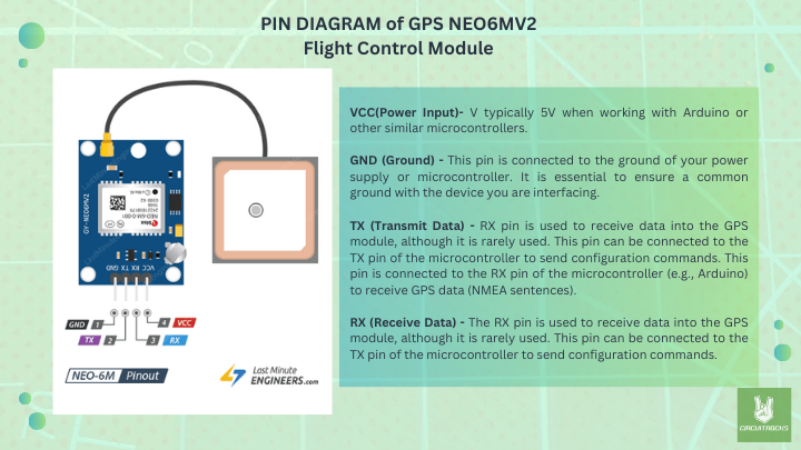
- VCC → 5V (Arduino)
- GND → GND (Arduino)
- TX → Pin 2 (Arduino)
- RX → Pin 3 (Arduino)
Note:
- Download the library: In the Arduino IDE, go to Sketch > Include Library > Manage Libraries…Search for TinyGPSPlus by Mikal Hart.
- Ensure proper connections between the GPS module and the Arduino.
- Outdoor testing: GPS modules require a clear view of the sky to receive satellite signals. Test the project outside in an open space rather than indoors.
- Time to lock: It may take a few minutes for the GPS module to get a satellite lock, especially during the first use. Be patient and wait for the GPS to acquire signals.
- Serial Monitor baud rate: Ensure the Serial Monitor in the Arduino IDE is set to 9600 baud to match the baud rate used in
Serial.begin(9600);in the code.
Code:
The setup() function, the Arduino communicates with both the GPS module and the serial monitor to display information. In the loop(), the GPS sends data continuously to the Arduino, which is decoded by the TinyGPS++ library. If valid data is received, the displayInfo() function shows the latitude, longitude, altitude, date, and time on the serial monitor. If no data is detected within 5 seconds, a “No GPS detected” message appears. You can expand the project by adding a display or logging the data to an SD card for future use.
#include <TinyGPS++.h>
#include <SoftwareSerial.h>
// Choose two Arduino pins to use for software serial
int RXPin = 2;
int TXPin = 3;
int GPSBaud = 9600;
// Create a TinyGPS++ object
TinyGPSPlus gps;
// Create a software serial port called "gpsSerial"
SoftwareSerial gpsSerial(RXPin, TXPin);
void setup()
{
  // Start the Arduino hardware serial port at 9600 baud
  Serial.begin(9600);
  // Start the software serial port at the GPS's default baud
  gpsSerial.begin(GPSBaud);
}
void loop()
{
  // This sketch displays information every time a new sentence is correctly encoded.
  while (gpsSerial.available() > 0)
    if (gps.encode(gpsSerial.read()))
      displayInfo();
  // If 5000 milliseconds pass and there are no characters coming in
  // over the software serial port, show a "No GPS detected" error
  if (millis() > 5000 && gps.charsProcessed() < 10)
  {
    Serial.println("No GPS detected");
    while(true);
  }
}
void displayInfo()
{
  if (gps.location.isValid())
  {
    Serial.print("Latitude: ");
    Serial.println(gps.location.lat(), 6);
    Serial.print("Longitude: ");
    Serial.println(gps.location.lng(), 6);
    Serial.print("Altitude: ");
    Serial.println(gps.altitude.meters());
  }
  else
  {
    Serial.println("Location: Not Available");
  }
  Serial.print("Date: ");
  if (gps.date.isValid())
  {
    Serial.print(gps.date.month());
    Serial.print("/");
    Serial.print(gps.date.day());
    Serial.print("/");
    Serial.println(gps.date.year());
  }
  else
  {
    Serial.println("Not Available");
  }
  Serial.print("Time: ");
  if (gps.time.isValid())
  {
    if (gps.time.hour() < 10) Serial.print(F("0"));
    Serial.print(gps.time.hour());
    Serial.print(":");
    if (gps.time.minute() < 10) Serial.print(F("0"));
    Serial.print(gps.time.minute());
    Serial.print(":");
    if (gps.time.second() < 10) Serial.print(F("0"));
    Serial.print(gps.time.second());
    Serial.print(".");
    if (gps.time.centisecond() < 10) Serial.print(F("0"));
    Serial.println(gps.time.centisecond());
  }
  else
  {
    Serial.println("Not Available");
  }
  Serial.println();
  Serial.println();
  delay(1000);
}
QUICK LINK
GPS Fundamentals with UBLOX NEO-6M GPS Chip


