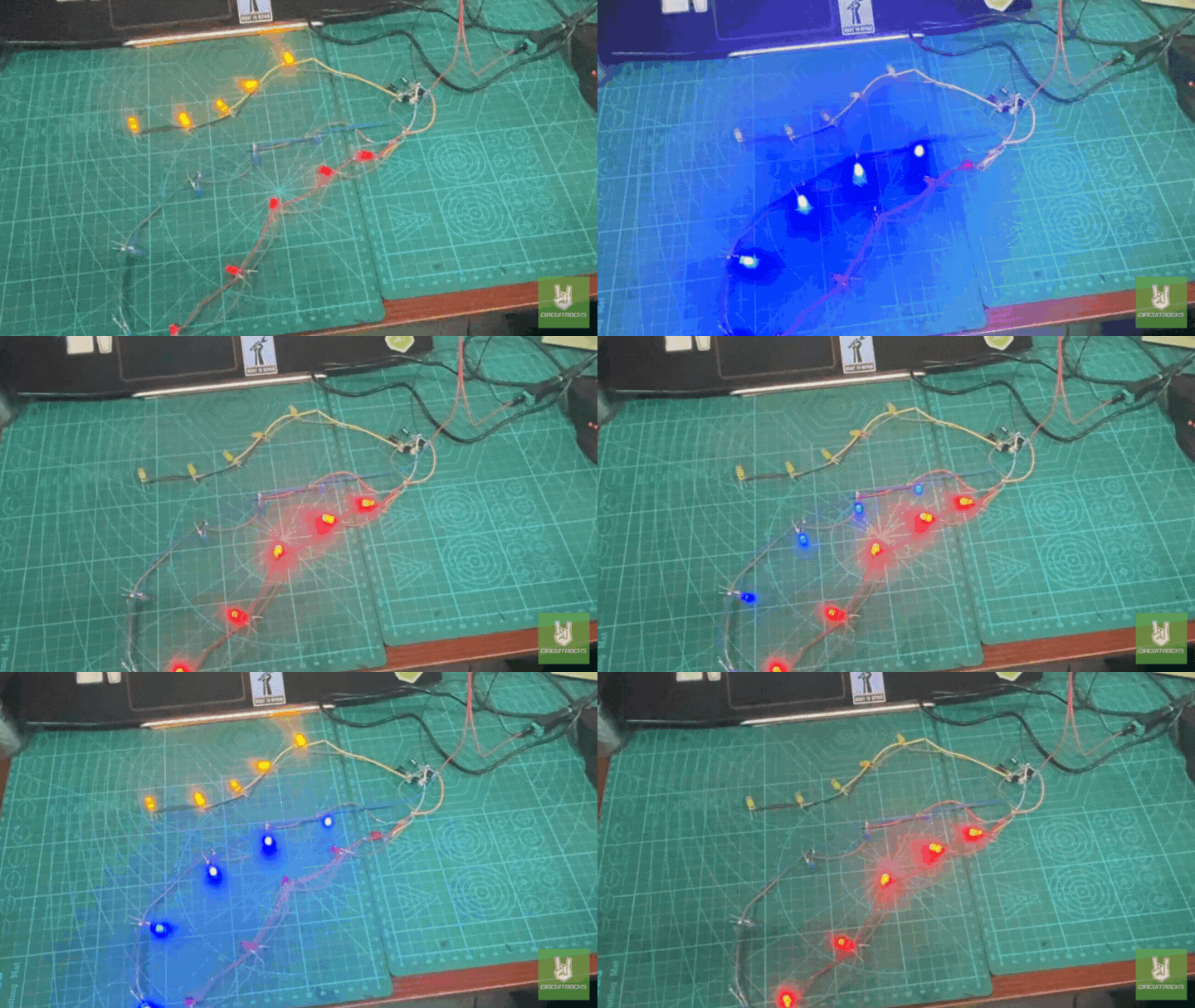
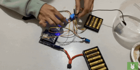
The LED Blinker Circuit is a beginner-friendly electronics project. Designed to demonstrate how LEDs can be controlled using timing components. This project focuses on alternating the blinking of yellow, blue, and red LEDs using two 555 timer ICs. It serves as a great introduction to how timing circuits work. It also how they can be applied in simple light-based displays.
The components used include two C555 timer ICs, a resistor, and capacitors. It also uses 5mm LEDs in three colors, jumper wires, a 12V battery, a DC female plug, and soldering tools. Such as soldering iron, soldering lead, and a third hand. Once the components are properly assembled and soldered. The circuit produces a continuous blinking pattern. Where each LED lights up alternately, showcasing the function of a well-timed pulse signal generated by the 555 timers.
Through this project, beginners can gain foundational knowledge of how timing components interact in a circuit. It offers practical experience in working with 555 timer ICs in astable mode. Understanding how resistors and capacitors affect timing intervals and practicing proper soldering and circuit assembly. The LED Blinker Circuit is a simple yet effective way. To explore core electronics principles through a fun and interactive setup.
Components:

- Capacitors
- Resistors Pack
- LED 5mm Set
- IC 555 Single Timer
- Jumper Wires
- Soldering Lead
- Soldering Iron
- 12v Adapter
- DC Female Plug
- Third Hand
Connections:

The schematic diagram shows a LED blinker circuit that works using two NE555 timer ICs. Each timer operates in astable mode, continuously generating ON and OFF pulses. The first NE555 (U1) controls the blinking of two LED columns — red and blue — connected to its output pins (pin 3 and pin 7). The second NE555 (U2) controls the third column (green LEDs) through its output (pin 3). Each timer uses a capacitor and resistor to set the speed of the blinking, creating an alternating light pattern.
The LEDs are grouped into three sets based on color: red (LED1–5), blue (LED6–10), and yellow (LED11–15). Each set lights up depending on the signal from the timer it’s connected to. The 220-ohm resistors connected to each LED limit the current to prevent damage. The power header at the bottom provides VCC and GND to power the entire circuit. As a result, the LEDs blink in a patterned sequence, controlled purely by the timing.


