
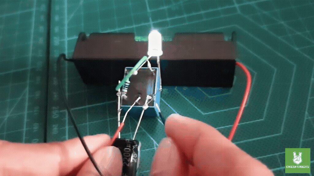
The Single LED Relay Oscillator Circuit is an easy electronics project for beginners. It uses a relay, a capacitor, a resistor, and a 3.7 V lithium battery to make an LED blink. For example, it is perfect for anyone who wants to learn how to blink an LED using a relay.
So, how does the circuit work? First, when you power it on, the battery charges the capacitor through the resistor. Meanwhile, as the capacitor charges, its voltage rises until it triggers the relay. Then, the relay switches states and connects the LED to the battery, lighting it up.
Next, the capacitor starts discharging through the relay coil. After that, when its voltage drops below a certain level, the relay returns to its original state and turns off the LED. As a result, this cycle of charging and discharging continues. Therefore, the relay keeps oscillating, which causes the LED to blink on and off.
Overall, this simple project clearly shows how basic electronic components work together to create a blinking LED. In addition, it helps you understand important concepts like charging, switching, and oscillation. For instance, you learn about voltage changes and relay activation.
By completing this project, learners gain practical skills in building circuits. They also develop a better understanding of basic electronic principles. Furthermore, this project encourages continued exploration and learning in the exciting world of electronics.
Components
Connections:
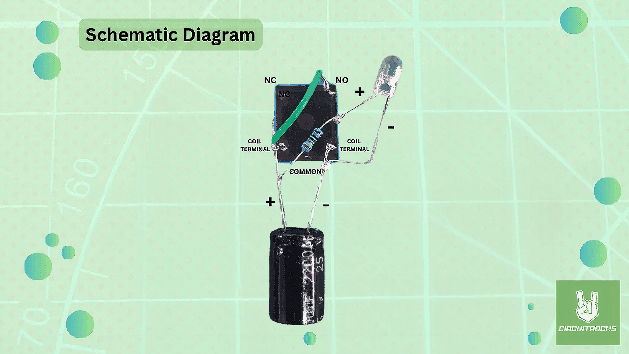
- LED: Connect the cathode (negative) of the LED to the negative terminal of the relay coil (Coil -). Attach the anode (positive) of the LED to one end of the 220-ohm resistor.
U Shape Jumper Wires
- Resistor: Link one end of the 220-ohm resistor to the anode (positive) of the LED. Connect the other end of the 220-ohm resistor to one of the relay coil terminals (Coil +).
- Capacitor: Attach the positive terminal of the capacitor to the same relay coil terminal where the resistor is connected (Coil +). Connect the negative terminal of the capacitor to the other relay coil terminal (Coil -).
- Relay: Use a jumper wire to connect the normally open (NO) terminal of the relay to the same relay coil terminal where the resistor and capacitor are connected (Coil +).
- Battery: Attach the positive of the lithium to the common (COM) terminal of the relay. Connect the negative of battery to the negative of the capacitor or negative terminal of the relay coil (Coil -) to power it.
Notes:
With basic tools like a Soldering Iron, Solder Lead, and a Third Hand with Magnifying Glass Tool. Creating the “Single LED Relay Oscillator Circuit” becomes an easy and accessible project for beginners. The soldering iron and solder lead enable precise and secure connections between components, ensuring the circuit functions correctly. The magnifying glass tool helps in viewing small parts and making accurate solder joints, making the assembly process straightforward and efficient. With these tools, even those new to electronics can successfully build this simple yet educational project.
QUICK LINK
Frequently Asked Questions
What does this Single LED Relay Oscillator Circuit tutorial cover?
The Single LED Relay Oscillator Circuit is an easy electronics project for beginners.
What's the working voltage of the Single LED Relay Oscillator Circuit?
Check the Sample Code section for the exact pinout — most maker-grade sensors run on 3.3V or 5V. Wire VCC to the matching rail, GND common with your MCU, data to a digital or analog pin.
Why does the Single LED Relay Oscillator Circuit read garbage or saturated values?
Three usual causes: wrong voltage rail, missing pull-up resistor on I2C lines (4.7k–10k to VCC), or a floating data pin. Double-check wiring against the diagram, then probe with a multimeter.