I really love the tutorial written by JP how to use ESP32 Deep Sleep. For the beginners who are not familiar with ESP-IDF and prefer to work with ArduinoIDE (or PlatformIO), I want to take JP’s lesson over to Arduino framework in a practical example.
In my other tutorial LoRa Gateway I showed you how to write the software for a simple LoRa gateway. This original code is not considering any power saving methods, so if you want to run your gateway from battery, it will not last very long.
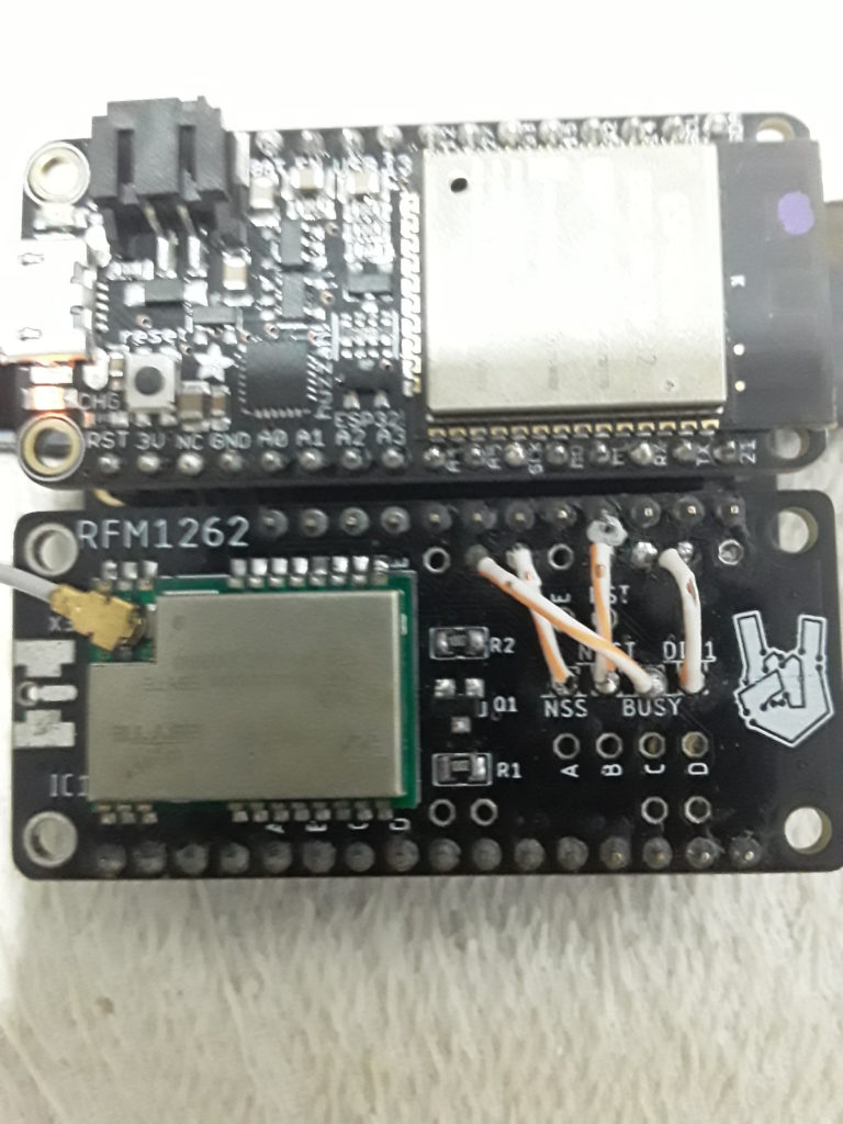
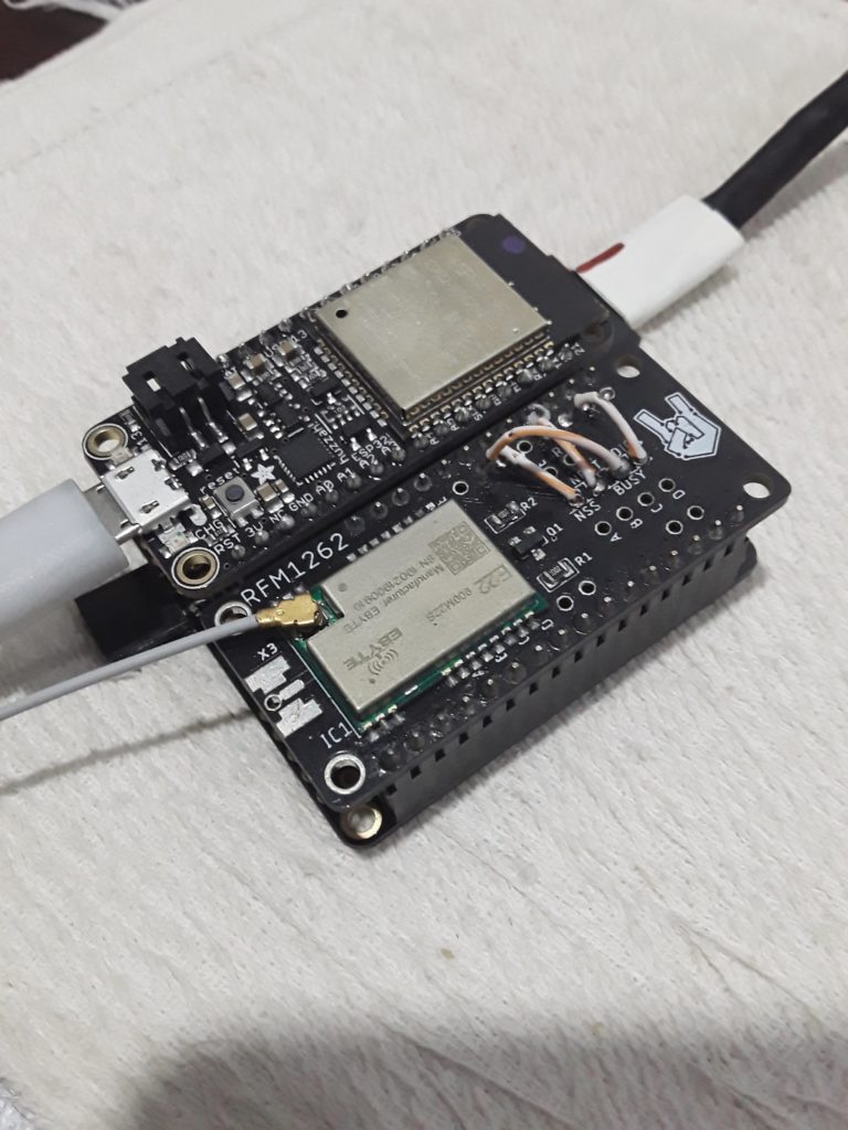
Now for the example, I used an Adafruit ESP32 Feather board and the brand-new Circuitrocks Alora RFM1262 board. The RFM1262 is a new Feather compatible LoRa board with the latest Semtech SX1262 LoRa transceiver.
How can we save energy? The gateway must be running all the time, as we do not know at what times the sensor nodes will send their data packages. But there are a few options to make the gateway battery powered.
Reduce CPU frequency
As JP mentioned in his tutorial, we can reduce the frequency of the ESP32. If programming in ESP-IDF, this is done by setting the CPU frequency in the menu config. For Arduino users this option is available as well with the simple function setCpuFrequencyMhz(). By default the ESP32 is running on a 240MHz clock. This can be reduced to
- 160MHz (WiFi and Bluetooth ok)
- 80MHz (WiFi and Bluetooth ok)
- 40MHz (no WiFi and no Bluetooth)
- 26MHz (no WiFi and no Bluetooth)
- 20MHz (no WiFi and no Bluetooth)
- 13MHz (no WiFi and no Bluetooth)
- 10MHz (no WiFi and no Bluetooth)
As you can already see in my comments, if you are planning to use WiFi or Bluetooth, you choices are limited. In the gateway we will need WiFi, because we need to forward the received LoRa data packages to the cloud.
So the preferred solution is to set the CPU frequency to 80MHz with the command setCpuFrequencyMhz(80);
Use Deep Sleep
JP’s tutorial shows us how to put the ESP32 into deep sleep and wake him up from a a touch-pad event. Here instead of the touch pad we will use an external signal. In deep sleep mode most parts of the ESP32 are turned off. That is what we are looking for.
To put the ESP32 into deep sleep the function is
esp_sleep_enable_ext0_wakeup(GPIO pin number, trigger edge);
followed by
esp_deep_sleep_start();
The first command tells the ESP32 on which GPIO it should look for a signal change defined by trigger edge (Rising or Falling). The second command will put the ESP32 into deep sleep mode.
We will use the SX1262 DIO1 signal as our external wake up signal. As DIO1 changes it status from Low to High on an event, we set the trigger edge to Rising.
esp_sleep_enable_ext0_wakeup((gpio_num_t)PIN_LORA_DIO_1, RISING);
esp_deep_sleep_start();
Receiving data while the ESP32 sleeps
But how do we receive LoRa messages while our ESP32 is sleeping? In the original gateway code we learned that we have to start listening to LoRa data packages with Radio.Rx(0), which will trigger an interrupt on DIO1 once the LoRa chip received a package and the ESP32 can read it from the SX126x. While waiting for a LoRa package, we kept the ESP32 running all the time just waiting for the interrupt (or a time out) to happen. Now instead of having the ESP32 awake while waiting for a data package, we will send it into deep sleep after we initialized the SX1262 in receive mode. But the function Radio.Rx() will stop after a given time with a RX timeout interrupt. So we need something else to avoid waking up the ESP32 without reason.
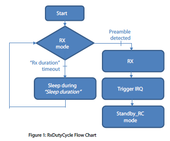
Luckily the Semtech SX126x LoRa transceivers have a very nice feature which is called RX Duty Cycle. When activating the RX Duty Cycle the SX126x will go into low power mode and wake up only for a short period of time to listen if any LoRa packages are about to be sent. Semtech has a good application note how this works, the document SX1261_AN1200.36_SX1261-2_RxDutyCycle_V1.0. I strongly recommend that you read this document before falling into a trap and your ESP32 is forever in deep sleep (unless you push the reset button). For those who don’t want to go through the whole document, I use some excerpts from the application to show you how RX Duty Cycle works and what settings need your special attention.
The principle of operation
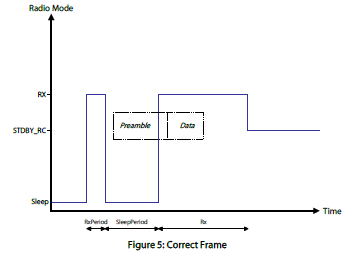
RxDutyCycle is a special RX mode that allows decreasing power consumption by putting periodically the radio in reception, while keeping the microcontroller in sleep mode. When a packet is received by the SX1261/2 it triggers an interrupt for the microcontroller in order to wake it up.
Calculation of sleep and receive time length
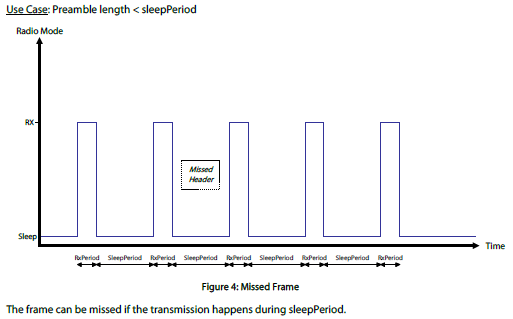
The important stuff is to calculate the “Rx duration” and the “Sleep duration” times. If you set your sleep time too long, the SX1262 might miss a preamble which is the beginning of a data package.
But how do we know the preamble length? Semtech has a nice tool, the “SX1261 Calculator Tool“. You definitly want to download and install this tool, because you need it to calculate the length of the sleep period.
Once you have the tool installed start it. In order to get the length of the preamble (which determines the length of the sleep period) you have to enter 4 parameters in the tool.
- Spreading factor
- Bandwidth
- Code Rate
- Preamble Length
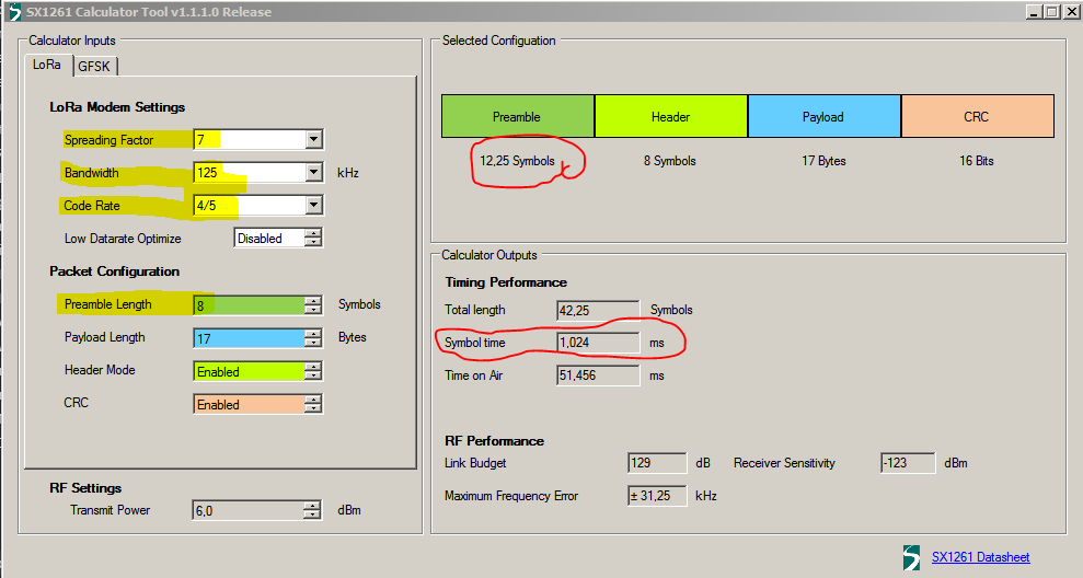
These parameters define the length of a single symbol.
Check the screenshot above where I marked in yellow the parameters you need to enter. The red circled numbers are what we need to calculate the preamble length.
In above example I set the SF to 7, the bandwidth to 125kHz, the CR to 4/5 and the preamble length to 8. That is what I will use later in the code.
You can see that with this settings, a symbol has a length of 1024ms and the preamble is 12.25 symbols long. That means that our preamble length is 1024ms * 12.25 = 12544ms long. So we know we have to set our sleep time shorter than that. To be able to catch at least 2 symbols when trying to catch the beginning of a data packet, I defined the sleep time to 10 symbols length which is 1024ms * 10 = 10240ms.
Ok, so now we know how long we can put the SX126x into sleep without missing a package. For the receive window, the time the SX126x is actually awake and listening, I chose a time of 2 symbols which gives us 1024ms * 2 = 2048ms.
If we calculated the sleep and receive times correct, we will be able to catch any incoming data packet, even in the worst case that we see only the last two symbols of the preamble.
Power savings
Now if you look on these two numbers, sleep time 10ms and awake (receive) time 2ms, that means that the SX126x is basically sleeping 8/10th of the time. And the ESP32 will be in deep sleep as well most of the time and only wake up after the SX1262 received a data package. That should give us a good power saving.
Important!
As the RESET and CHIP-SELECT inputs of the SX1262 are floating while the ESP32 is in deep sleep, you will have to add pull-up resistors to this 2 inputs. I chose 10k Ohm resistors which works just fine.
Example code
Now we put the whole thing into a working example. To keep it simple, the example will just print the received data over the Serial debug output. At that point you will have to add code to process the data, send it to the cloud or whatever you want to do with it.
Prerequisite for the example code is that you have the SX126x-Arduino library version 1.0.5 installed. Only from this version on the deep sleep for the ESP32 is supported.
You can install the library over the library manager of ArduinoIDE or PlatformIO. Just search for SX126x-Arduino. It has some nice examples too for LoRa communication, LoRaWan and even a full deep sleep example
Looking into the code, you will see that the first thing to do is to check why the ESP32 started the code.
// Check the reasons the CPU's are started. We need this later to decide if a full initialization
// of the SX126x is required or if the chip just woke up triggered by an interrupt from the SX126x
RESET_REASON cpu0WakeupReason = rtc_get_reset_reason(0);
RESET_REASON cpu1WakeupReason = rtc_get_reset_reason(1);
We need to do this, because on a new start, we have to do a full initialization of the SX1262 chip, which includes a reset of the chip. This is what lora_hardware_init(hwConfig); does. But when we wake up from deep sleep after a data package was received, we do not want to do the reset, because it would erase the received data. lora_hardware_re_init(hwConfig); is what we want to use in this case.
// Initialize the LoRa chip
if ((cpu0WakeupReason == DEEPSLEEP_RESET) || (cpu1WakeupReason == DEEPSLEEP_RESET))
{
	// Wake up reason was a DEEPSLEEP_RESET, which means we were woke up by the SX126x
	Serial.println("Starting lora_hardware_re_init");
	lora_hardware_re_init(hwConfig);
}
else
{
	// Other wake up reasons mean we need to do a complete initialization of the SX126x
	Serial.println("Starting lora_hardware_init");
	lora_hardware_init(hwConfig);
}
Next is the initialization of the radio functions. Again, after a power-up start or a reset, a full initialization is required (frequency, RX and TX settings, …), while after waking up from deep sleep, we only need to do a basic initialization and can start reading the data from the SX1262.
if ((cpu0WakeupReason == DEEPSLEEP_RESET) || (cpu1WakeupReason == DEEPSLEEP_RESET))
{
	// Wake up reason was a DEEPSLEEP_RESET, just re-initialize the callbacks
	Serial.println("Trying to handle SX1262 event after deep sleep wakeup");
	// Re-Initialize the Radio
	Radio.ReInit(&RadioEvents);

	// Handle LoRa events to find out what the reason for the wake up was and handle the data
	Radio.IrqProcessAfterDeepSleep();
}
else
{
	Serial.println("Power on reset, reinitialize the Radio");
	// Other wake up reasons mean we need to do a complete initialization of the SX126x
	// Initialize the Radio
	Radio.Init(&RadioEvents);

	// Set Radio channel
	Radio.SetChannel(RF_FREQUENCY);

	// Set Radio TX configuration
	Radio.SetTxConfig(MODEM_LORA, TX_OUTPUT_POWER, 0, LORA_BANDWIDTH,
				LORA_SPREADING_FACTOR, LORA_CODINGRATE,
				LORA_PREAMBLE_LENGTH, LORA_FIX_LENGTH_PAYLOAD_ON,
				true, 0, 0, LORA_IQ_INVERSION_ON, TX_TIMEOUT_VALUE);

		// Set Radio RX configuration
	Radio.SetRxConfig(MODEM_LORA, LORA_BANDWIDTH, LORA_SPREADING_FACTOR,
				LORA_CODINGRATE, 0, LORA_PREAMBLE_LENGTH,
				LORA_SYMBOL_TIMEOUT, LORA_FIX_LENGTH_PAYLOAD_ON,
				0, true, 0, 0, LORA_IQ_INVERSION_ON, true);
}
The function Radio.IrqProcessAfterDeepSleep(); will check the IRQ status of the SX1262 and then call the approriate call back function, which in this case will be OnRxDone()
/**@brief Function to be executed on Radio Rx Done event
 */
void OnRxDone(uint8_t *payload, uint16_t size, int16_t rssi, int8_t snr)
{
	Serial.println("Receive finished");
	char debugOutput[1024];
	for (int idx = 0; idx < size; idx++)
	{
		sprintf(&debugOutput[(idx * 2)], "%02X", payload[idx]);
	}
	Serial.printf("Data: %s\n", debugOutput);

	// Now its up to YOU to do something with the data

	// LoRa receive finished, go back to bed
	goToSleep();
}
The OnRxDone function receives a pointer to the date, the size of the packet, the signal strength and the signal to noise ratio.
As said earlier, here we just print out the data, but in a real application, we would start WiFi, connect to an AP and send the data to the cloud.
After the data is processed, we go back into sleep by calling goToSleep();
The other Radio even callbacks are not used in this example. But as you can see, just in case they are called, all of them end up with a call to goToSleep().
/**
 * Put SX126x into RX mode and ESP32 into deep-sleep mode
 */
void goToSleep(void)
{
	// Start waiting for data package
	Radio.Standby();
	SX126xSetDioIrqParams(IRQ_RX_DONE | IRQ_RX_TX_TIMEOUT,
				IRQ_RX_DONE | IRQ_RX_TX_TIMEOUT,
				IRQ_RADIO_NONE, IRQ_RADIO_NONE);
	// To get maximum power savings we use Radio.SetRxDutyCycle instead of Radio.Rx(0)
	// This function keeps the SX1261/2 chip most of the time in sleep and only wakes up short times
	// to catch incoming data packages
	Radio.SetRxDutyCycle(2 * 1024 * 1000 * 15.625, 10 * 1024 * 1000 * 15.625);

	// Go back to bed
	Serial.println("Start sleeping");
    // Make sure the DIO1, RESET and NSS GPIOs are hold on required levels during deep sleep
	rtc_gpio_set_direction((gpio_num_t)PIN_LORA_DIO_1, RTC_GPIO_MODE_INPUT_ONLY);
	rtc_gpio_pulldown_en((gpio_num_t)PIN_LORA_DIO_1);
	// Setup deep sleep with wakeup by external source
	esp_sleep_enable_ext0_wakeup((gpio_num_t)PIN_LORA_DIO_1, RISING);
	// Finally set ESP32 into sleep
	esp_deep_sleep_start();
}
In goToSleep, the first thing we do is to initiate the RX Duty Cycle function of the SX1262 with the above calculated sleep and receive times.
Radio.SetRxDutyCycle (receive time in 15.625 uS fragments, sleep time in 15.625 uS fragments) is the function. So we use 2 symbols for the receive time and 10 symbols for the sleep time.
Radio.SetRxDutyCycle(2 * 1024 * 1000 * 15.625, 10 * 1024 * 1000 * 15.625);
If you are wondering about the * 15.625 in the calculation, the SX1262 expects the time values not in milliseconds, but in fractions of 15.625 to match its internal clock.
Then to avoid that the SX1262 gets confused by some random levels on its RESET or NSS (chip select) inputs, we ask the RTC (one of the few things awake while the ESP32 is in deep sleep) to keep these GPIOs on a fixed level.
And last, we setup the deep sleep with external wake up interrupt and finally put the ESP32 into deep sleep.
And here is the complete code:
#include <Arduino.h>
#include <SPI.h>
#include <Ticker.h>
#include <rom/rtc.h>
#include <driver/rtc_io.h>
#include <SX126x-Arduino.h>

#define LOG_ON

// ESP32 Feather - SX126x pin configuration
/** LORA RESET */
int PIN_LORA_RESET = 32;
/** LORA DIO_1 */
int PIN_LORA_DIO_1 = 14;
/** LORA SPI BUSY */
int PIN_LORA_BUSY = 27;
/** LORA SPI CS */
int PIN_LORA_NSS = 33;
/** LORA SPI CLK */
int PIN_LORA_SCLK = 5;
/** LORA SPI MISO */
int PIN_LORA_MISO = 19;
/** LORA SPI MOSI */
int PIN_LORA_MOSI = 18;

/** LED on level */
#define LED_ON HIGH
/** LED off level */
#define LED_OFF LOW

// Define LoRa parameters
#define RF_FREQUENCY 915000000  // Hz
#define TX_OUTPUT_POWER 22		// dBm
#define LORA_BANDWIDTH 0		// [0: 125 kHz, 1: 250 kHz, 2: 500 kHz, 3: Reserved]
#define LORA_SPREADING_FACTOR 7 // [SF7..SF12]
#define LORA_CODINGRATE 1		// [1: 4/5, 2: 4/6,  3: 4/7,  4: 4/8]
#define LORA_PREAMBLE_LENGTH 8  // Same for Tx and Rx
#define LORA_SYMBOL_TIMEOUT 0   // Symbols
#define LORA_FIX_LENGTH_PAYLOAD_ON false
#define LORA_IQ_INVERSION_ON false
#define RX_TIMEOUT_VALUE 3000
#define TX_TIMEOUT_VALUE 3000

#define BUFFER_SIZE 512 // Define the payload size here

/** Lora events */
static RadioEvents_t RadioEvents;

/** LoRa HW configuration */
hw_config hwConfig;

/** CAD repeat counter */
uint8_t cadRepeat;

// Event declarations
/** LoRa transmit success */
void OnTxDone(void);
/** LoRa receive success */
void OnRxDone(uint8_t *payload, uint16_t size, int16_t rssi, int8_t snr);
/** LoRa transmit timeout */
void OnTxTimeout(void);
/** LoRa receive timeout */
void OnRxTimeout(void);
/** LoRa receive error */
void OnRxError(void);
/** LoRa CAD finished */
void OnCadDone(bool cadResult);

/** Print reset reason */
void print_reset_reason(RESET_REASON reason);

/** Node ID */
uint8_t deviceId[8];

/**
 * Put SX126x into RX mode and ESP32 into deep-sleep mode
 */
void goToSleep(void)
{
	// Start waiting for data package
	Radio.Standby();
	SX126xSetDioIrqParams(IRQ_RX_DONE | IRQ_RX_TX_TIMEOUT,
						  IRQ_RX_DONE | IRQ_RX_TX_TIMEOUT,
						  IRQ_RADIO_NONE, IRQ_RADIO_NONE);
	// To get maximum power savings we use Radio.SetRxDutyCycle instead of Radio.Rx(0)
	// This function keeps the SX1261/2 chip most of the time in sleep and only wakes up short times
	// to catch incoming data packages
	Radio.SetRxDutyCycle(2 * 1024 * 1000 * 15.625, 10 * 1024 * 1000 * 15.625);

	// Go back to bed
#ifdef LOG_ON
	Serial.println("Start sleeping");
#endif
    // Make sure the DIO1, RESET and NSS GPIOs are hold on required levels during deep sleep
	rtc_gpio_set_direction((gpio_num_t)PIN_LORA_DIO_1, RTC_GPIO_MODE_INPUT_ONLY);
	rtc_gpio_pulldown_en((gpio_num_t)PIN_LORA_DIO_1);
	// Setup deep sleep with wakeup by external source
	esp_sleep_enable_ext0_wakeup((gpio_num_t)PIN_LORA_DIO_1, RISING);
	// Finally set ESP32 into sleep
	esp_deep_sleep_start();
}

/**
 * ESP32 startup
 */
void setup()
{
#ifdef LOG_ON
	// Start serial communication
	Serial.begin(115200);
#endif

	// Check the reasons the CPU's are started. We need this later to decide if a full initialization
	// of the SX126x is required or if the chip just woke up triggered by an interrupt from the SX126x
	RESET_REASON cpu0WakeupReason = rtc_get_reset_reason(0);
	RESET_REASON cpu1WakeupReason = rtc_get_reset_reason(1);

#ifdef LOG_ON
	Serial.println("CPU0 reset reason: ");
	print_reset_reason(cpu0WakeupReason);

	Serial.println("CPU1 reset reason: ");
	print_reset_reason(cpu1WakeupReason);
#endif

	// Show we are awake
	pinMode(LED_BUILTIN, OUTPUT);
	digitalWrite(LED_BUILTIN, LED_ON);

	// Define the HW configuration between MCU and SX126x
	hwConfig.CHIP_TYPE = SX1262_CHIP;		  // Example uses an eByte E22 module with an SX1262
	hwConfig.PIN_LORA_RESET = PIN_LORA_RESET; // LORA RESET
	hwConfig.PIN_LORA_NSS = PIN_LORA_NSS;	 // LORA SPI CS
	hwConfig.PIN_LORA_SCLK = PIN_LORA_SCLK;   // LORA SPI CLK
	hwConfig.PIN_LORA_MISO = PIN_LORA_MISO;   // LORA SPI MISO
	hwConfig.PIN_LORA_DIO_1 = PIN_LORA_DIO_1; // LORA DIO_1
	hwConfig.PIN_LORA_BUSY = PIN_LORA_BUSY;   // LORA SPI BUSY
	hwConfig.PIN_LORA_MOSI = PIN_LORA_MOSI;   // LORA SPI MOSI
	hwConfig.RADIO_TXEN = -1;				  // LORA ANTENNA TX ENABLE
	hwConfig.RADIO_RXEN = -1;				  // LORA ANTENNA RX ENABLE
	hwConfig.USE_DIO2_ANT_SWITCH = true;	  // Example uses an CircuitRocks Alora RFM1262 which uses DIO2 pins as antenna control
	hwConfig.USE_DIO3_TCXO = true;			  // Example uses an CircuitRocks Alora RFM1262 which uses DIO3 to control oscillator voltage
	hwConfig.USE_DIO3_ANT_SWITCH = false;	 // Only Insight ISP4520 module uses DIO3 as antenna control

	// Slowing down the ESP32 to 1/4 of its speed saves more energy
	setCpuFrequencyMhz(80);

	// Initialize the LoRa chip
	if ((cpu0WakeupReason == DEEPSLEEP_RESET) || (cpu1WakeupReason == DEEPSLEEP_RESET))
	{
		// Wake up reason was a DEEPSLEEP_RESET, which means we were woke up by the SX126x
#ifdef LOG_ON
		Serial.println("Starting lora_hardware_re_init");
#endif
		lora_hardware_re_init(hwConfig);
	}
	else
	{
		// Other wake up reasons mean we need to do a complete initialization of the SX126x
#ifdef LOG_ON
		Serial.println("Starting lora_hardware_init");
#endif
		lora_hardware_init(hwConfig);
	}

	// Initialize the Radio callbacks
	RadioEvents.TxDone = OnTxDone;
	RadioEvents.RxDone = OnRxDone;
	RadioEvents.TxTimeout = OnTxTimeout;
	RadioEvents.RxTimeout = OnRxTimeout;
	RadioEvents.RxError = OnRxError;
	RadioEvents.CadDone = OnCadDone;

	if ((cpu0WakeupReason == DEEPSLEEP_RESET) || (cpu1WakeupReason == DEEPSLEEP_RESET))
	{
		// Wake up reason was a DEEPSLEEP_RESET, just re-initialize the callbacks
#ifdef LOG_ON
		Serial.println("Trying to handle SX1262 event after deep sleep wakeup");
#endif
		// Initialize the Radio
		Radio.ReInit(&RadioEvents);

		// Handle LoRa events to find out what the reason for the wake up was and handle the data
		Radio.IrqProcessAfterDeepSleep();
	}
	else
	{
#ifdef LOG_ON
		Serial.println("Power on reset, reinitialize the Radio");
#endif
		// Other wake up reasons mean we need to do a complete initialization of the SX126x
		// Initialize the Radio
		Radio.Init(&RadioEvents);

		// Set Radio channel
		Radio.SetChannel(RF_FREQUENCY);

		// Set Radio TX configuration
		Radio.SetTxConfig(MODEM_LORA, TX_OUTPUT_POWER, 0, LORA_BANDWIDTH,
						  LORA_SPREADING_FACTOR, LORA_CODINGRATE,
						  LORA_PREAMBLE_LENGTH, LORA_FIX_LENGTH_PAYLOAD_ON,
						  true, 0, 0, LORA_IQ_INVERSION_ON, TX_TIMEOUT_VALUE);

		// Set Radio RX configuration
		Radio.SetRxConfig(MODEM_LORA, LORA_BANDWIDTH, LORA_SPREADING_FACTOR,
						  LORA_CODINGRATE, 0, LORA_PREAMBLE_LENGTH,
						  LORA_SYMBOL_TIMEOUT, LORA_FIX_LENGTH_PAYLOAD_ON,
						  0, true, 0, 0, LORA_IQ_INVERSION_ON, true);
	}

	// goToSleep will start listening to LoRa data packages and put the ESP32 into deep sleep
	goToSleep();
}

/**
 * ESP32 main task
 */
void loop()
{
}

/**@brief Function to be executed on Radio Tx Done event
 */
void OnTxDone(void)
{
#ifdef LOG_ON
	Serial.println("Transmit finished");
#endif
	// LoRa TX finished, go back to bed
	goToSleep();
}

/**@brief Function to be executed on Radio Rx Done event
 */
void OnRxDone(uint8_t *payload, uint16_t size, int16_t rssi, int8_t snr)
{
#ifdef LOG_ON
	Serial.println("Receive finished");
#endif
	char debugOutput[1024];
	for (int idx = 0; idx < size; idx++)
	{
		sprintf(&debugOutput[(idx * 2)], "%02X", payload[idx]);
	}
	Serial.printf("Data: %s\n", debugOutput);

	// Now its up to YOU to do something with the data

	// LoRa receive finished, go back to bed
	goToSleep();
}

/**@brief Function to be executed on Radio Tx Timeout event
 */
void OnTxTimeout(void)
{
#ifdef LOG_ON
	Serial.println("Transmit timeout");
#endif
	// LoRa TX failed, go back to bed
	goToSleep();
}

/**@brief Function to be executed on Radio Rx Timeout event
 */
void OnRxTimeout(void)
{
#ifdef LOG_ON
	Serial.println("Receive timeout");
#endif
	// LoRa RX failed, go back to bed
	goToSleep();
}

/**@brief Function to be executed on Radio Rx Error event
 */
void OnRxError(void)
{
#ifdef LOG_ON
	Serial.println("Receive error");
#endif
	// LoRa RX failed, go back to bed
	goToSleep();
}

/**@brief Function to be executed on Radio Rx Error event
 */
void OnCadDone(bool cadResult)
{
	cadRepeat++;
	Radio.Standby();
	if (cadResult)
	{
#ifdef LOG_ON
		Serial.printf("CAD returned channel busy %d times\n", cadRepeat);
#endif
		if (cadRepeat < 6)
		{
			// Retry CAD
			Radio.Standby();
			SX126xSetCadParams(LORA_CAD_08_SYMBOL, LORA_SPREADING_FACTOR + 13, 10, LORA_CAD_ONLY, 0);
			SX126xSetDioIrqParams(IRQ_CAD_DONE | IRQ_CAD_ACTIVITY_DETECTED,
								  IRQ_CAD_DONE | IRQ_CAD_ACTIVITY_DETECTED,
								  IRQ_RADIO_NONE, IRQ_RADIO_NONE);
			Radio.StartCad();
		}
		else
		{
			// LoRa is too busy? Go to bed
			goToSleep();
		}
	}
	else
	{
#ifdef LOG_ON
		Serial.printf("CAD returned channel free after %d times\n", cadRepeat);
#endif
		// If we need to send something, it should be done here
		// after CAD found the channel available
	}
}

/**
 * Print the reset reason.
 * Just for better understanding.
 * Not required for the function of the app
 */
void print_reset_reason(RESET_REASON reason)
{
	switch (reason)
	{
	case 1:
		Serial.println("POWERON_RESET");
		break; /**<1, Vbat power on reset*/
	case 3:
		Serial.println("SW_RESET");
		break; /**<3, Software reset digital core*/
	case 4:
		Serial.println("OWDT_RESET");
		break; /**<4, Legacy watch dog reset digital core*/
	case 5:
		Serial.println("DEEPSLEEP_RESET");
		break; /**<5, Deep Sleep reset digital core*/
	case 6:
		Serial.println("SDIO_RESET");
		break; /**<6, Reset by SLC module, reset digital core*/
	case 7:
		Serial.println("TG0WDT_SYS_RESET");
		break; /**<7, Timer Group0 Watch dog reset digital core*/
	case 8:
		Serial.println("TG1WDT_SYS_RESET");
		break; /**<8, Timer Group1 Watch dog reset digital core*/
	case 9:
		Serial.println("RTCWDT_SYS_RESET");
		break; /**<9, RTC Watch dog Reset digital core*/
	case 10:
		Serial.println("INTRUSION_RESET");
		break; /**<10, Instrusion tested to reset CPU*/
	case 11:
		Serial.println("TGWDT_CPU_RESET");
		break; /**<11, Time Group reset CPU*/
	case 12:
		Serial.println("SW_CPU_RESET");
		break; /**<12, Software reset CPU*/
	case 13:
		Serial.println("RTCWDT_CPU_RESET");
		break; /**<13, RTC Watch dog Reset CPU*/
	case 14:
		Serial.println("EXT_CPU_RESET");
		break; /**<14, for APP CPU, reseted by PRO CPU*/
	case 15:
		Serial.println("RTCWDT_BROWN_OUT_RESET");
		break; /**<15, Reset when the vdd voltage is not stable*/
	case 16:
		Serial.println("RTCWDT_RTC_RESET");
		break; /**<16, RTC Watch dog reset digital core and rtc module*/
	default:
		Serial.println("NO_MEAN");
	}
}

